PLT165-SM
Linear Stages
High load linear stage (ball screw), travel 100 - 500 mm, rep ± 3.9 µm, load 25 kg, speed 80 mm/s

Precision stage with stepper motor
The PLT165-SM features an easy-to-operate stepper motor in combination with a high precision ball screw. The slim design of the linear stage, with a width of just 165 mm, allows it to be used in restricted spaces.
Ideal for vertical applications
Thanks to its protective casing, it can be used in industrial environments. A ball screw drive in combination with an electromagnetic brake offers maximum self-retention force, allowing a vertical position to be maintained even when the device is de-energized. The PLT165 can be easily combined with the lifting stage HT160.
Universal application
The PLT165-SM is suitable for positioning sensors or lenses in applications that place strict demands on lifetime and reliability, such as laser engineering and metrology.
| PLT165 | -100-SM | -200-SM | -300-SM | -400-SM | -500-SM | |
| Travel | [mm] | 100 | 200 | 300 | 400 | 500 |
| Repeatability unidirectional | [μm] | ± 3.9 | ± 3.9 | ± 3.9 | ± 3.9 | ± 3.9 |
| Repeatability bidirectional | [μm] | ± 4.4 | ± 4.4 | ± 4.4 | ± 4.4 | ± 4.4 |
| Accuracy | [μm] | ± 7.7 | ± 9.9 | ± 12 | ± 14 | ± 15.9 |
| Flatness | [μm] | ± 3 | ± 6 | ± 9 | ± 12 | ± 15 |
| Straightness | [μm] | ± 1.5 | ± 3 | ± 4.5 | ± 6 | ± 7.5 |
| Positioning speed | [mm/s] | 40 | 40 | 40 | 40 | 40 |
| Max. speed | [mm/s] | 80 | 80 | 80 | 80 | 80 |
| Max. acceleration | [m/s2] | 0.8 | 0.8 | 0.8 | 0.8 | 0.8 |
| Max. load Fx | [N] | 250 | 250 | 250 | 250 | 250 |
| Max. load Fy | [N] | 520 | 520 | 520 | 520 | 520 |
| Max. load Fz | [N] | 520 | 520 | 520 | 520 | 520 |
| Max. torque Mx | [Nm] | 13 | 13 | 13 | 13 | 13 |
| Max. torque My | [Nm] | 19 | 19 | 19 | 19 | 19 |
| Max. torque Mz | [Nm] | 25 | 25 | 25 | 25 | 25 |
| Pitch | [µrad] | ± 20 | ± 30 | ± 35 | ± 40 | ± 45 |
| Yaw | [µrad] | ± 10 | ± 14 | ± 17 | ± 20 | ± 20 |
| Resolution | [µm] | 1.563 | 1.563 | 1.563 | 1.563 | 1.563 |
| L1 | [mm] | 400 | 500 | 600 | 700 | 800 |


Related Products


Almost all atmospheric standard stages are anodized with UHV lubrication for residual pressures up to 10-6 mbar and min. cleanroom class ISO 6 - or even better - available. Further stages for more demanding environments up to cleanroom class ISO 2, vacuum up to 10E-11 mbar or hard radiation you will find here:
Overview Clean Room & Vacuum XY Stages Get in touch with our technical consultant
XY stages are basically high-precision positioning systems that are used to move objects in two dimensions (X and Y axes). They are used in a variety of applications, such as microscopy, manufacturing and automation technology. The architecture of our motorized XY systems can be categorized into four basic concepts:
- Stacked stages (“Ritter Sport architecture”)
- Crossed linear stages (“cross architecture”)
- Inverted pyramid (“cone architecture”)
- Pyramid (“pyramid architecture”)
Most XY stages are built according to the principle of the plate stack, sometimes also called “Ritter Sport architecture”. They have a particularly compact, square design and meet the expectations of a cross table.
However, they move apart during operation and then take up more space in two dimensions around the travel distance. The overhanging of the massive plates leads to bending, which reduces accuracy. As the design rules require the guides to be longer than the lateral distance, there is unused material on the sides of the individual travel directions. This causes the stage itself to be comparatively heavy, but it provides no benefit and merely causes the cross stage to bend additionally during travel. This results in a strong positional dependency of the bending and thus of the precision.
The cross architecture is easy to implement and is created by bolting linear motion stages together in a criss-cross pattern. Movement in one direction takes place across the center footprint. Space must be reserved accordingly in this direction. The advantage is that the plates are less bulky, reducing overhangs and thus bending and the impact on precision. As there is no material spilling over the sides of the crossed individual stages, there is less warping. The space gained can be used for cable routing for the upper axis. This results in less warping depending on the position and thus in greater precision.
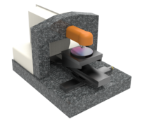
Microscope stages are usually constructed as an inverted pyramid, resembling a “sugar cone” in shape. Compared to other architectures, this is particularly compact, flat and light. The drives can easily be hidden under the overhanging plates, which is particularly advantageous for mobile devices. This architecture is sufficient for applications in which the load is always applied in the center, for example in hardness testing stages. However, as with the plate stack architecture, the plates move apart and then take up additional space in two dimensions around the travel range. This means that the inverse pyramid has disadvantages comparable to those of the plate stack architecture.
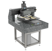
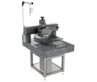
The fourth architecture is the strict pyramid structure, which is characterized by its large appearance and thus does not meet the usual expectations of an XY Stage. The advantage of this solution is that the plates do not move apart during operation, so that the stage always takes up the same space. The flat support of the lower plate on the base structure forms a very rigid base for the entire system. In addition, there is no unused or overhanging material on the sides. The guide carriages always run completely on rails supported by metal and the guidance ratio is always maintained. In this way, the pyramid architecture is characterized by excellent accuracy values and extremely low deviations during movement and under different loads.
Steinmeyer Mechatronik GmbH mainly uses aluminum for the structure of XY Stages, as it provides the necessary flexural rigidity.
Optionally, various special materials and surface finishes are possible. Whether anodized, aluminum cleaned bare, bilatal or nickel for optimal process capability (e.g. particularly high degrees of purity, resistance to cleaning with chemicals in the field of life science), whether UV, DUV or EUV (X-ray, gamma on request). In special cases, titanium is also used for magnet-free systems.
Depending on the requirements, various drive systems can be used. This can be recognized as an abbreviation in the name below:
- Ground ball screws or lead screws with SM (stepper motor), DC motor or AC servo.
- Electrodynamic linear motors (ironless or iron-core).
- Piezomotors such as Piezo-Legs® or Nanomotion®.
Incremental scales made of steel or Zerodur® or Zeromet® are used as a feedback system in most cases. While this is sufficient for accuracy in the single-digit micrometer range, it makes sense to use interferometric position feedback for accuracy requirements below one micrometer. In systems with “open loop”, i.e. without a measuring system, only precision in the double-digit micrometer range can be achieved; however, due to the simpler controller and the lack of a measuring system, this is the more cost-effective solution.
Are you looking for a technical solution for your application?
Get your first 3D Design in a few days:

Katja Weißbach
Consulting
T +49 351 88585-64
E-Mail

Ronald Schulze
Consulting, Project Management & Engineering
T +49 351 88585-67
E-Mail

Francisco Samuel
Consulting &
Project Management
T +49 351 88585-85
E-Mail

Elger Matthes
Consulting, Concepts, Innovation & Engineering
T +49 351 88585-82
E-Mail
Our references