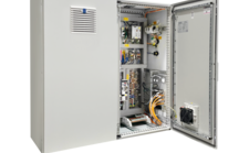
PLT165-DLM
Linear Stages
High performance stage (linear motor), travel 200 - 750 mm, rep ± 0.4 µm, load 6 kg, speed 1155 mm/s

Robust precision stage
The drive concept of this linear stage is based on a linear motor, thus allowing high acceleration and speed. This makes the linear stage ideal for horizontal applications where these characteristics are required.
Made for industrial applications
With a width of 165 mm, the PLT165 is the narrowest in its series. It is used as a single axis or as the top axis in multi-axis systems. The protect housing and metal strip cover design ensure protection against dust and particles in industrial environments.
Versatile fields of application
The PLT165 with dynamic linear motor is suitable for all areas of industry in which the precise adjustment of probes, sensors or optics is required - such as, for example, lacer machining, semiconductor technology or measurement egineering.
| PLT165 | -200-DLM-L | -300-DLM-L | -400-DLM-L | -500-DLM-L | -750-DLM-L | |
| Travel | [mm] | 200 | 300 | 400 | 500 | 750 |
| Repeatability unidirectional | [μm] | ± 0.4 | ± 0.4 | ± 0.4 | ± 0.4 | ± 0.4 |
| Repeatability bidirectional | [μm] | ± 0.5 | ± 0.5 | ± 0.5 | ± 0.5 | ± 0.5 |
| Accuracy | [μm] | ± 1.5 | ± 1.8 | ± 2 | ± 2.2 | ± 2.8 |
| Flatness | [μm] | ± 6 | ± 9 | ± 12 | ± 15 | ± 25 |
| Straightness | [μm] | ± 3 | ± 4.5 | ± 6 | ± 7.5 | ± 11 |
| Positioning speed | [mm/s] | 470 | 530 | 580 | 630 | 770 |
| Max. speed | [mm/s] | 705 | 795 | 870 | 945 | 1155 |
| Max. acceleration | [m/s2] | 9.5 | 11 | 12 | 13 | 15 |
| Max. load Fx | [N] | 60 | 60 | 60 | 60 | 60 |
| Max. load Fy | [N] | 520 | 520 | 520 | 520 | 520 |
| Max. load Fz | [N] | 520 | 520 | 520 | 520 | 520 |
| Max. torque Mx | [Nm] | 13 | 13 | 13 | 13 | 13 |
| Max. torque My | [Nm] | 19 | 19 | 19 | 19 | 19 |
| Max. torque Mz | [Nm] | 25 | 25 | 25 | 25 | 25 |
| Pitch | [µrad] | ± 30 | ± 35 | ± 40 | ± 45 | ± 55 |
| Yaw | [µrad] | ± 14 | ± 17 | ± 20 | ± 20 | ± 25 |
| Resolution | [µm] | 0.1 | 0.1 | 0.1 | 0.1 | 0.1 |
| L1 | [mm] | 500 | 600 | 700 | 800 | 1050 |


Related Products


Almost all atmospheric standard stages are unanodized with UHV lubrication for residual pressures up to 10-6 mbar and min. cleanroom class ISO 6 - or even better - available. Further stages for more demanding environments up to cleanroom class ISO 2, vacuum up to 10E-11 mbar or hard radiation you will find here:
Overview Clean Room & Vacuum XY Stages Get in touch with our technical consultant
XY stages are basically high-precision positioning systems that are used to move objects in two dimensions (X and Y axes). They are used in a variety of applications, such as microscopy, manufacturing and automation technology. The architecture of our motorized XY systems can be categorized into four basic concepts:
- Stacked stages (“Ritter Sport architecture”)
- Crossed linear stages (“cross architecture”)
- Inverted pyramid (“cone architecture”)
- Pyramid (“pyramid architecture”)
Most XY stages are built according to the principle of the plate stack, sometimes also called “Ritter Sport architecture”. They have a particularly compact, square design and meet the expectations of a cross table.
However, they move apart during operation and then take up more space in two dimensions around the travel distance. The overhanging of the massive plates leads to bending, which reduces accuracy. As the design rules require the guides to be longer than the lateral distance, there is unused material on the sides of the individual travel directions. This causes the stage itself to be comparatively heavy, but it provides no benefit and merely causes the cross stage to bend additionally during travel. This results in a strong positional dependency of the bending and thus of the precision.
The cross architecture is easy to implement and is created by bolting linear motion stages together in a criss-cross pattern. Movement in one direction takes place across the center footprint. Space must be reserved accordingly in this direction. The advantage is that the plates are less bulky, reducing overhangs and thus bending and the impact on precision. As there is no material spilling over the sides of the crossed individual stages, there is less warping. The space gained can be used for cable routing for the upper axis. This results in less warping depending on the position and thus in greater precision.
Microscope stages are usually constructed as an inverted pyramid, resembling a “sugar cone” in shape. Compared to other architectures, this is particularly compact, flat and light. The drives can easily be hidden under the overhanging plates, which is particularly advantageous for mobile devices. This architecture is sufficient for applications in which the load is always applied in the center, for example in hardness testing stages. However, as with the plate stack architecture, the plates move apart and then take up additional space in two dimensions around the travel range. This means that the inverse pyramid has disadvantages comparable to those of the plate stack architecture.
The fourth architecture is the strict pyramid structure, which is characterized by its large appearance and thus does not meet the usual expectations of an XY Stage. The advantage of this solution is that the plates do not move apart during operation, so that the stage always takes up the same space. The flat support of the lower plate on the base structure forms a very rigid base for the entire system. In addition, there is no unused or overhanging material on the sides. The guide carriages always run completely on rails supported by metal and the guidance ratio is always maintained. In this way, the pyramid architecture is characterized by excellent accuracy values and extremely low deviations during movement and under different loads.
Steinmeyer Mechatronik GmbH mainly uses aluminum for the structure of XY Stages, because it efficiently dissipates local heat and quickly reaches a thermally stable state. This is a prerequisite for stable, precise systems. The lower stiffness of aluminum compared to steel is compensated by a slightly higher height of the stages or the use of hollow profiles. Note: An aluminum beam and a steel beam sag equally under their own weight!
In special cases, titanium is also used for magnet-free systems.
What surfaces are available?
Various surface options are available. Depending on the application, anodized and cleaned, alternative colors, aluminum cleaned and bare, bilatal or nickel are available for optimal process suitability (e.g. particularly high degrees of purity, resistance to cleaning with chemicals in the field of life science). Special surfaces are often necessary for UV, DUV or EUV (X-ray, gamma on request).
Depending on the requirements, various drive systems can be used. This can be recognized as an abbreviation in the name below:
- Ground ball screws or lead screws with SM (stepper motor), DC motor or AC servo.
- Electrodynamic linear motors (ironless or iron-core).
- Piezomotors such as Piezo-Legs® or Nanomotion®.
Incremental scales made of steel or Zerodur® or Zeromet® are used as a feedback system in most cases. While this is sufficient for accuracy in the single-digit micrometer range, it makes sense to use interferometric position feedback for accuracy requirements below one micrometer. In systems with “open loop”, i.e. without a measuring system, only precision in the double-digit micrometer range can be achieved; however, due to the simpler controller and the lack of a measuring system, this is the more cost-effective solution.
Are you looking for a technical solution for your application?
Get your first 3D Design in a few days:

Katja Weißbach
Consulting
T +49 351 88585-64
E-Mail

Ronald Schulze
Consulting, Project Management & Engineering
T +49 351 88585-67
E-Mail

Francisco Samuel
Consulting &
Project Management
T +49 351 88585-85
E-Mail

Elger Matthes
Consulting, Concepts, Innovation & Engineering
T +49 351 88585-82
E-Mail
Our references